Serial Killer
A photographic tour of the current Serial Killer is available
here. The status as of the writing of
this paragraph (July 97) is that a couple undergrads are writing software
to take SK to the 1997 AAAI competition, where the task includes vacuuming
confetti. I added vacuuming hardware for them, visible in the photographs.
Robots at Dartmouth
(COSC 88/184, Spring 1996)
As you can see, this page has Web Rot. The abbreviated end of the story is that the
robot went to the competition in Portland, and completed the task, but only after the
show-me deadline, and so didn't get to show his stuff to the world. Sad, since this
$1000 robot could do the same task that $50,000 robots were doing with oodles more
hardware. Anyway, the robot looks a little different now (14" aluminum chassis, still
the same style), with much better motors, including 3000 cpr shaft encoders. It's
being used next term (Winter 1997) for the AI class.
(SpeedyLinks: MIT's old IC,
Newton Labs,
Motorola.)
A guide to Serial Killer for other users.
My odometry talk for class.
The team:
- Artyom Lifshits
- David Zipkin
- David Villarama
- Jon Howell
We wanted a tough name for our wimpy robot, so Tim
suggested "Killer." But then that sounded unpleasant, so we thought
"Serial Killer" would sound nicer.
Different views of our robot.
(120K)
Killer is a basic $500 kit based on a Motorola 6811 microcontroller. In
these views (129K), Killer is the
completed basic kit. It includes:
- differential drive locomotion
- shaft encoders which measure wheel rotation (odometry)
- two photodetectors (light level)
- front-looking near-infrared detector, with two transmitters
(senses near obstacles, 6")
- microphone (measures ambient audio level; we don't have enough memory or
processor to sample audio)
- three bump sensors (measures contact with obstacles. Skirt not pictured.)
- serial interface
- piezo buzzer
- 32-character LCD display
A diagram of the main logic board.
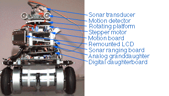
We have added these extra sensors and equipment to the robot:
- sonar (measures distances from 10" up to maybe 10')
- stepper motor (aims a rotary tray containing pyro and sonar through
360 degrees)
- zero-detect infrared encoder (aligns stepper motor)
- ultrasonic motion detector (detects humans 4-7m away)
- 9V battery for ultrasonic motion detector
- lead-acid battery to provide longer supply and greater current
draw for motors
A diagram of the planned (and now executed)
additions to the board.
One of the tough problems is the huge uncertainty in the low-cost sensors
we are using. Look at a note on odometry which
describes a technique for determining position from wheel movement.
So it turns out that the robot was getting very confused about odometry
because the floating point package included with the Interactive C pcode
interpreter has a buggy divide routine. (Can you say "Pentium?" But this
stuff was written in 1986, heh heh. :v) 1.0/1.0=0.5. Oops. See a
page of notes Jon is taking on various topics,
such as reassembling the pcoder. This will let us fix the FP routines,
and possibly even optimize things for space a little.