View bot
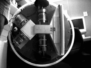 This bottom view shows the wheel motors and wheels, and the vacuum system.
Confetti enters through the wide slot at the front (right side of the image),
filling the triangular chamber and the center rectangular chamber. A wire
screen inside the chamber provides lots of sucking surface area. Suction
is provided by the two Dustbuster fans at the rear (left). The center chamber
is covered by an aluminum door which is controlled by a servo (like those
in model airplanes). The servo is inside the diamond-shaped chamber, and not
visible without the door open and a dental mirror. :v)
This bottom view shows the wheel motors and wheels, and the vacuum system.
Confetti enters through the wide slot at the front (right side of the image),
filling the triangular chamber and the center rectangular chamber. A wire
screen inside the chamber provides lots of sucking surface area. Suction
is provided by the two Dustbuster fans at the rear (left). The center chamber
is covered by an aluminum door which is controlled by a servo (like those
in model airplanes). The servo is inside the diamond-shaped chamber, and not
visible without the door open and a dental mirror. :v)
In a modification performed after these photos were taken, a second
servo was installed outside the vacuum chamber, with a shaft leading
into the chamber and a wiper blade that was to help push the chaff
out the door. It didn't help much.
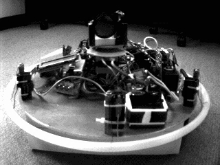 You are looking at the front of the robot. Visible on the left of the image
are the LCD display and the pushbutton inputs. The three vertical posts around
the perimeter are switches to detect bumps. In the center you can see the
sonar turret and the stepper motor below it which positions it. On the right
in the foreground is the battery pack for the Dustbuster fans. Below the
chassis you can see the front of the vacuum chamber.
You are looking at the front of the robot. Visible on the left of the image
are the LCD display and the pushbutton inputs. The three vertical posts around
the perimeter are switches to detect bumps. In the center you can see the
sonar turret and the stepper motor below it which positions it. On the right
in the foreground is the battery pack for the Dustbuster fans. Below the
chassis you can see the front of the vacuum chamber.
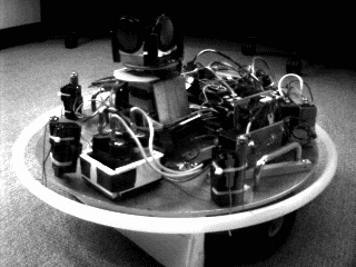 You can see both sonar transducers from here.
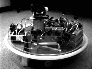 A second sonar transducer is visible from this angle, although only
one transducer is actually used, as the I/O lines on the CPU were needed
for other purposes.
A second sonar transducer is visible from this angle, although only
one transducer is actually used, as the I/O lines on the CPU were needed
for other purposes.
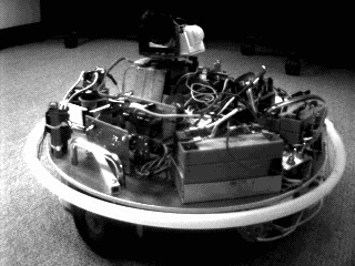 The vertical boards on the left are (foreground) the Dustbuster relay
board and servo power supply and (background) optical isolators for the
H-bridges that deliver power to the wheel motors. The isolators prevent
high-voltage inductance spikes from working their way back to the CPU,
where they confuse it.
The vertical boards on the left are (foreground) the Dustbuster relay
board and servo power supply and (background) optical isolators for the
H-bridges that deliver power to the wheel motors. The isolators prevent
high-voltage inductance spikes from working their way back to the CPU,
where they confuse it.
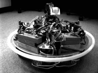 The motor battery pack on the left drives the wheel motors and the relay
that switches on the Dustbuster motors. The Dustbusters are just visible
below the chassis. The switches in the foreground are logic and battery
power and reset.
The motor battery pack on the left drives the wheel motors and the relay
that switches on the Dustbuster motors. The Dustbusters are just visible
below the chassis. The switches in the foreground are logic and battery
power and reset.
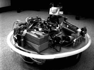 The rear bump switch is visible, as well as the back of one of the Dustbuster
fans (below the chassis). The big fray of wires on the top is the (barely
resolvable) stack of electronics. There are five printed circuit boards
in the stack, with lots of stray wires wandering off to various I/O boards
mounted elsewhere on the robot. Visible on the sonar turret is the motion
detector, which provides a 1-bit output saying that there is or isn't
motion in its view.
The rear bump switch is visible, as well as the back of one of the Dustbuster
fans (below the chassis). The big fray of wires on the top is the (barely
resolvable) stack of electronics. There are five printed circuit boards
in the stack, with lots of stray wires wandering off to various I/O boards
mounted elsewhere on the robot. Visible on the sonar turret is the motion
detector, which provides a 1-bit output saying that there is or isn't
motion in its view.
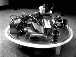 The batteries on the left supply power to the logic components and to
the stepper motor and vacuum chamber door servo.
The batteries on the left supply power to the logic components and to
the stepper motor and vacuum chamber door servo.
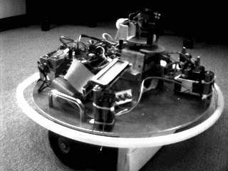 Here the battery packs and elecronics are coming into view on the left.
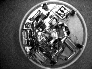 This top-down view shows the front of the robot pointing Northeast.